The label that should have stayed in the shop
A complete build record for turning a surplus Solum retail label into a Home Assistant-backed Codex status display: EFR32 recovery, Pico 2 flashing, S3+C6 radio architecture, no-solder decisions, wiring failures and the path to a homelab enclosure.
The label that should have stayed in the shop§
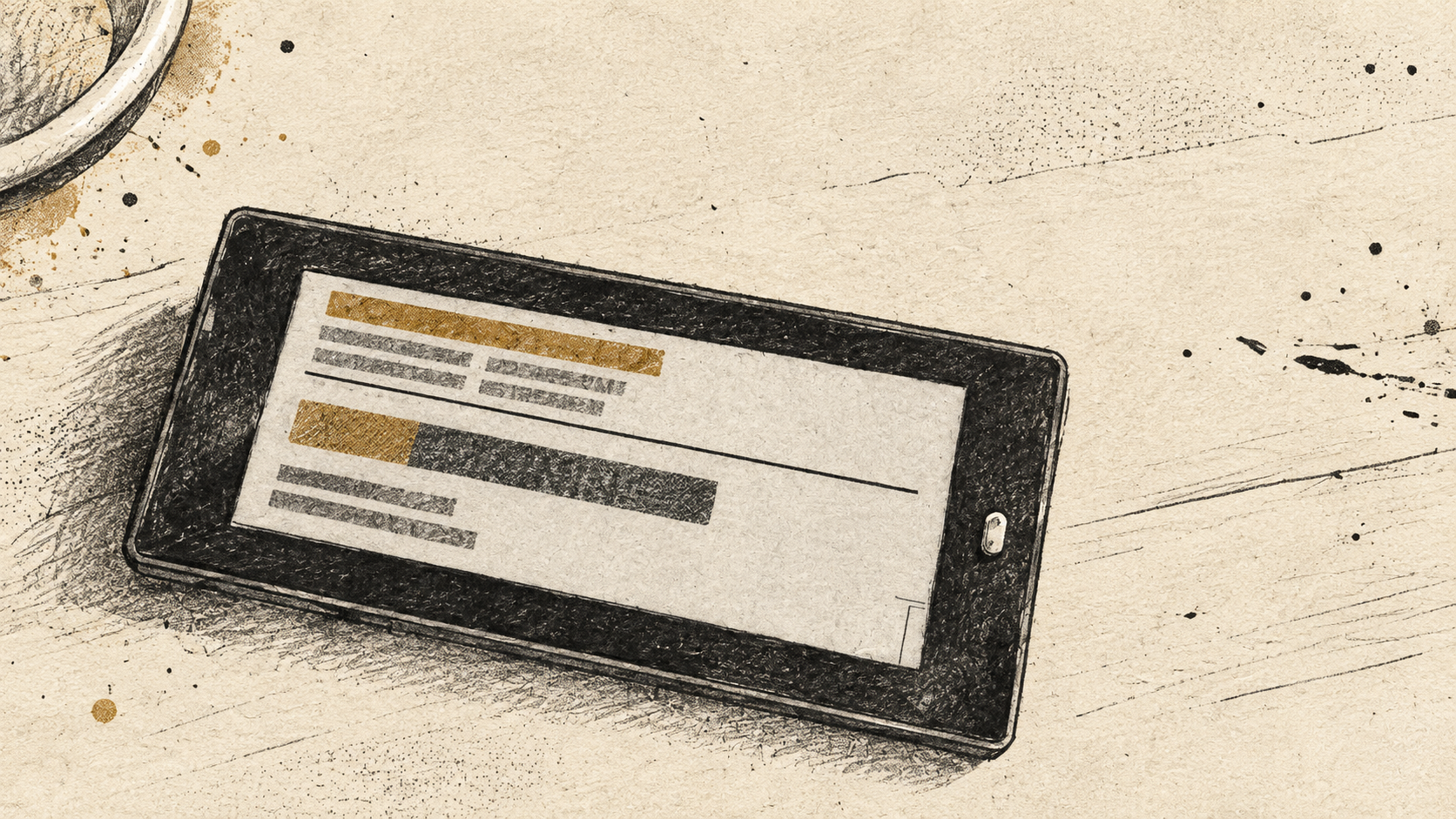
A shop gave me a surplus electronic shelf label. It was one of the e-ink units normally clipped to a supermarket shelf: a 2.9-inch Solum Newton M3 with a barcode and a device identifier still visible on screen.
It is now a low-power Codex status display. Every thirty minutes it shows the current usage windows exposed by my authenticated Codex session, the relevant reset time, and a deliberately separate summary of token activity. Home Assistant owns the display update. The screen itself is not on the internet and has no account credentials.
That description leaves out most of the work.
The project started as “can this shop label be repurposed?” It became a research task, a firmware-recovery exercise, a small radio-network build, a Home Assistant integration, a Mac-side usage collector, and a lesson in why a no-solder constraint can be a productive engineering decision.
This is the full build record: the hardware I identified, the routes I ruled out, the guides I used, the failure modes, and the design decisions that made the final display useful rather than merely novel.
What I was given§
The front of the label identified it as an M3 2.9-inch Newton BWR display. The rear label gave the more useful information:
- manufacturer: Solum
- model:
EL029F3WRA - manufacture date: May 2023
- device identifier: a unique label serial number
- regulatory identifiers for the radio hardware
That was enough to stop treating it as a generic “e-ink screen”. It is a retail electronic shelf label, or ESL. In its intended environment, it is part of a managed fleet. A store access point sends it a finished image over low-power radio. The label spends most of its time asleep, waking only to check for work. It retains the last image without continuous power.
That makes it a better fit for a small status display than a normal tablet or wall dashboard. It is readable in daylight, has no backlight, makes no noise, and does not invite interaction. It is an output device with one job.
The label was free. The system around it was not free in either time or thought.
Before doing anything: identify the chip, and decide whether it is disposable§
The first research path was OpenEPaperLink, an open-source ecosystem for repurposing commercial e-paper tags. Its general guide for SiLabs M3 Newton labels explains why model identification matters.
These labels can use more than one radio family. The guide distinguishes Silicon Labs EFR32 devices from Nordic nRF devices and warns that the flashing process differs. The dedicated Pico 2 guide for Solum EFR32BG22 labels calls out the expected marking:
BG22
C222WG
That is the EFR32BG22C222. It is the version required for this route.
There is another consequence. Retail labels are usually debug-locked. The manufacturer lock prevents someone reading the original firmware. If the device allows unauthenticated unlock, unlocking it erases the retail firmware. The OpenEPaperLink documentation recommends saving user data before flashing if there is any chance it will be needed for later support.
I did not need to preserve the retailer’s firmware. The label was a donated surplus device. That made the decision straightforward, but it is an important warning for anyone repeating this: do not run an erase command on a label you expect to return to its original system.
The first question: Raspberry Pi, Pico, or something else?§
I had a Raspberry Pi 4 already running Grafana, an ESP32-C6 development board, and a Raspberry Pi Pico 2 W. The early question was whether the Pi could simply replace the Pico and whether a USB radio dongle could replace the rest of the access-point hardware.
In principle, a Raspberry Pi can take part. In practice, it was the wrong direction for this build.
OpenEPaperLink’s access-point guide explicitly notes that a Raspberry Pi plus a CC2530 radio is theoretically possible, but misses much of the project’s better-supported access-point behaviour. The recommendation is an ESP32-based AP.
The Pi also does not solve the first job: unlocking and flashing an EFR32 Series 2 chip. The key issue is not whether a computer has GPIO pins. It is whether the debugger can speak the EFR32 Series 2 Debug Challenge Interface. The Pico 2 guide records that Pi GPIO bit-banging with stock OpenOCD did not work because the missing piece was protocol support, not timing.
That made the Pico 2 W the right tool for the initial flash. It is inexpensive, works as a CMSIS-DAP debug probe once loaded with the correct firmware, and is useful enough to keep in the toolkit afterwards.
Flashing the Pico 2 W as a debug probe§
The Pico process was simple, but then the first issue so I thought happened.
With the BOOTSEL button held while plugging it in, the Pico appears as a USB mass-storage volume. I copied Raspberry Pi’s debugprobe_on_pico2.uf2 file to that volume. It then rebooted and disappeared from Finder, which can look like a failure if you are expecting it to remain a drive.
It had not failed. It had stopped being a USB disk and become a debugger.
On macOS, I needed to stop just going off the status of the leds and actual confirming what the USB device attached was:
Debugprobe on Pico (CMSIS-DAP)The Pico 2 instructions describe the same end state: the Pico should identify as “Raspberry Pi Debugprobe on Pico (CMSIS-DAP)”.
USB storage is only the bootloader personality. CMSIS-DAP is the working requirement.
The programming jig and the five contacts§
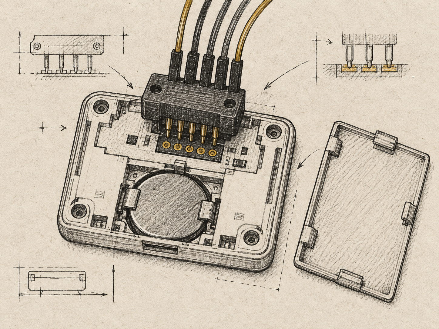
The tag’s test pads sit under the battery cover. This means its normal CR2450 battery cannot remain in place during programming. The tag needs external 3.3V while being probed. It also means that reset is not optional: the OpenEPaperLink documentation is clear that reset is mandatory during the unlock procedure.
A community STL for a universal pogo-pin jig made this substantially safer. The jig holds the contacts against the test pads instead of requiring wires to be soldered directly to the label.
The five connections from the Pico 2 W are:
| Pico 2 W | Debug function | Label test pad |
|---|---|---|
| GP2 | SWCLK | CLK |
| GP3 | SWDIO | DIO |
| GP4 | nRESET | RST |
| GND | ground | GND |
| 3V3 OUT | power | VCC |
The wiring is small, but the principle is larger: verify power, clock, data, reset and ground separately. A custom printed jig turns that from a fiddly one-off needing 5 hands to a simpler procedure.
The macOS OpenOCD detour§
The community guide was written and tested on Linux. My host was a Mac.
The first OpenOCD build did not simply work. The dependency configuration wanted J-Link support and stopped because libjaylink was missing. After that, Apple Clang rejected a source warning that the project’s usual Linux build tolerated. This was an unglamorous build-tool problem, but it really mattered as the stock OpenOCD cannot unlock this chip family.
The needed implementation is the community EFR32 Series 2 OpenOCD fork. Its usefulness is the efm32s2_dci_device_erase command. That command handles the debug unlock over the correct DCI interface, rather than relying on timing tricks or undocumented register writes.
Once built, the OpenOCD binary confirmed that it had the expected EFR32 Series 2 target scripts. Then the next failure was electrical rather than software.
At 1 MHz, OpenOCD could see the Pico but could not read the target ID register:
Error: Error connecting DP: cannot read IDRThe sensible response was not to change everything. The connection path was already mostly proven: macOS could see the Pico, OpenOCD could initialise CMSIS-DAP, and the jig was contacting the label. I lowered SWD speed to 500 kHz and tried again.
That produced:
Info : SWD DPIDR 0x6ba02477
Info : [efm32s2.cpu] Cortex-M33 r0p4 processor detected
Info : [efm32s2.cpu] target has 8 breakpoints, 4 watchpoints
The label had been reached.
The guide describes the expected locked-device state: the debug lock is normal, and the useful capability check is whether device erase is enabled. The erase is destructive. It removes the stock Solum firmware and frees the chip for the replacement firmware.
After erase, the label had to be fully power-cycled before the debug interface became accessible again. Only then was the OpenEPaperLink _FULL.s37 image programmed.
detected part: BG22C222
flash size = 352 KiB
Programming Finished
Verified OK
Resetting Target
“Verified OK” was the success needed. An e-ink label gives almost no feedback when its firmware is wrong. A verified flash is better evidence than a reassuring progress bar.
Reproducible command record: Mac, Pico 2 W and EFR32BG22§
This is the command path I used on macOS. It is intentionally recorded as a build log rather than presented as an infallible installer: the OpenOCD fork is community-maintained, the Pico guide was tested on Linux, and compiler errors vary by macOS and Xcode version.
1. Put debugprobe firmware on the Pico 2 W§
With the Pico disconnected, hold BOOTSEL, plug in USB, then release the button. It should appear as a removable RP2350 or RPI-RP2 volume.
mkdir -p ~/eink
cd ~/eink

curl -L -O \
  https://github.com/raspberrypi/debugprobe/releases/latest/download/debugprobe_on_pico2.uf2

cp "$HOME/Downloads/debugprobe_on_pico2.uf2" /Volumes/RP2350/
The volume disappears after the copy because the Pico reboots into debug-probe mode. Verify the new USB identity:
ioreg -p IOUSB -w 0 | grep -iE 'debug|pico|raspberry|cmsis'Expected result:
Debugprobe on Pico (CMSIS-DAP)2. Build the EFR32 Series 2-capable OpenOCD§
Install the build dependencies, then prepare the community fork:
brew install autoconf automake libtool libusb hidapi pkg-config

cd ~/eink
git clone https://github.com/knieriem/openocd-efm32-series2.git
cd openocd-efm32-series2
sh setup-openocd-src.sh
cd openocd
The first macOS build attempted support for debug adapters I did not own and stopped on an optional J-Link dependency. The useful minimum is CMSIS-DAP support for the Pico. Configure with unused adapter families disabled, install, then check the resulting binary:
./configure \
  --enable-cmsis-dap \
  --enable-cmsis-dap-v2 \
  --disable-jlink \
  --disable-ftdi \
  --disable-stlink \
  --prefix="$HOME/eink/openocd-efm32s2-dist"

make -j"$(sysctl -n hw.ncpu)"
make install

../openocd-efm32s2-dist/bin/openocd --version
If the compiler stops on an unrelated adapter driver, do not assume the tag wiring is at fault. Reconfigure with the unnecessary driver disabled, or use the fork’s minimal build script. The requirement is simply that the final binary reports CMSIS-DAP support and includes target/efm32s2.cfg.
3. Test the tag connection at the slower speed that worked§
Set a shell variable so subsequent commands remain legible:
OCD="$HOME/eink/openocd-efm32s2-dist/bin/openocd"
SCRIPTS="$HOME/eink/openocd-efm32s2-dist/share/openocd/scripts"

"$OCD" -s "$SCRIPTS" \
  -f interface/cmsis-dap.cfg \
  -c "transport select swd" \
  -c "adapter speed 500" \
  -f target/efm32s2.cfg \
  -c "init" \
  -c "targets" \
  -c "exit"
The published guide begins at 1000 kHz. This label did not respond there, returning cannot read IDR. At 500 kHz, it reported SWD DPIDR 0x6ba02477 and identified a Cortex-M33.
4. Erase the retail firmware and unlock the chip§
This is the destructive step. It permanently removes the original label firmware. Run it only after deciding that repurposing the tag is acceptable.
"$OCD" -s "$SCRIPTS" \
  -f interface/cmsis-dap.cfg \
  -c "transport select swd" \
  -c "adapter speed 500" \
  -f target/efm32s2.cfg \
  -c "init" \
  -c "efm32s2_dci_device_erase" \
  -c "exit"
Disconnect external 3.3V and the Pico wiring, wait a few seconds, then reconnect both. The power cycle is required before the unlocked debug interface behaves normally.
5. Flash the OpenEPaperLink tag firmware§
Download the current full firmware image from the Tag_FW_EFR32xG22 releases. The first flash should use the _FULL.s37 file because it includes bootloader and application.
"$OCD" -s "$SCRIPTS" \
  -f interface/cmsis-dap.cfg \
  -c "transport select swd" \
  -c "adapter speed 500" \
  -f target/efm32s2.cfg \
  -c "init" \
  -c "halt" \
  -c "program $HOME/Downloads/SOLUM_AUTODETECT_FULL_v40.s37 verify reset exit"
Do not move on until the end of the log says Verified OK.
Access point research: why the answer became two boards§
Flashing the label is only half the system. It still needs an access point that speaks Wi-Fi to Home Assistant and IEEE 802.15.4 to the tag.
I looked at the usual choices:
- a ready-made Mini AP, which would be the cleanest option if it were in stock
- a Raspberry Pi with a CC2530 or CC2531 USB radio
- a single ESP32-C6 board
- a generic ESP32-S3 and ESP32-C6 pair
- a pre-made commercial access point
The ready-made route was tempting, but availability was poor. The Pi-plus-dongle route was possible but not the recommended OpenEPaperLink path. The single C6 seemed particularly appealing because it has Wi-Fi and 802.15.4 hardware on one chip.
The project documentation explains why that does not work for this access-point role. The C6 cannot run Wi-Fi communication and continuously listen in IEEE 802.15.4 mode at the same time. An AP has to be available for unsolicited tag messages, so the radio needs to listen continuously.
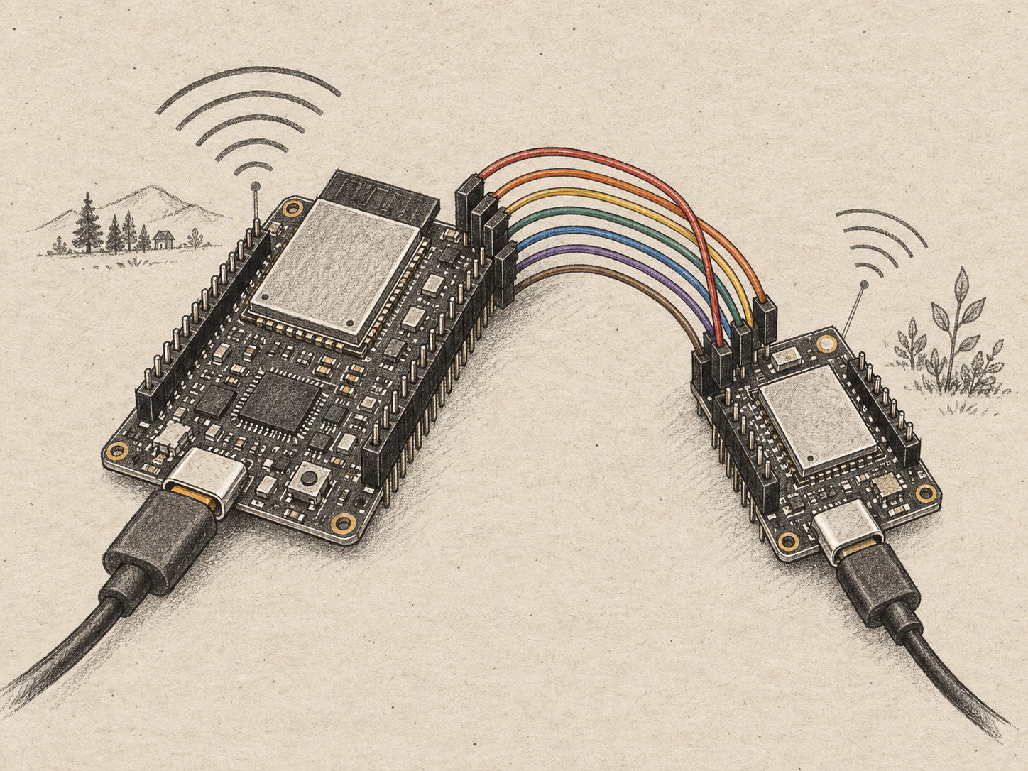
That is why the normal design is two chips:
- an ESP32-S3 handles the AP application, web interface and Wi-Fi
- an ESP32-C6 remains dedicated to 802.15.4 radio duty
The OpenEPaperLink guide calls the DIY combination a “Spaghetti AP”, effectively a clone of the Yellow AP. It also says the supported S3 configuration should have 16MB flash and 8MB PSRAM, while the C6 needs at least 4MB flash.
The specific boards I settled on were:
| Component | What it does | Why it was selected |
|---|---|---|
| ESP32-S3-N16R8 | Primary AP controller | Correct 16MB flash and 8MB PSRAM profile for the Yellow AP build |
| Waveshare ESP32-C6-DEV-KIT-N8 | Dedicated 802.15.4 radio | Supported C6 class, USB-C, pre-soldered headers |
| Raspberry Pi Pico 2 W | One-time tag debug probe | Cheap CMSIS-DAP route for the BG22 |
| Dupont jumper wires | S3 to C6 interconnect | Visible, movable and replaceable |
| Printed pogo jig | Label flashing interface | Avoids soldering onto the label |
The pre-soldered headers deserve more attention than they usually get in build guides.
I am not yet comfortable soldering. That narrowed the purchasing options. It meant avoiding the C6 I already had because it had bare pads, and finding boards with headers already fitted. It also removed the apparently cheap choice of a generic S3 plus an unsoldered breakout board.
That was not a compromise in the finished system. It was a good first-build decision.
A two-board layout with jumper wires costs a little more desk space and looks less finished than a custom PCB. It also makes every signal visible, replaceable and testable. When learning a new radio stack, that is a meaningful advantage. It prevented “I might have damaged a board” from becoming the default explanation for every problem.
Installing the access point§
The OpenEPaperLink web installer supports the appropriate access-point firmware without requiring a local PlatformIO toolchain.
The selected primary-board image was Yellow AP, which is the S3 plus C6 design. The installer asks for the serial device exposed by the board, uploads the firmware, then hands over to the AP setup flow for Wi-Fi configuration.
The C6 was then flashed for its radio role. The OpenEPaperLink build guide distinguishes the two firmware jobs: primary S3 firmware and C6 radio firmware. It also records that the primary S3 pins should follow an existing supported access-point layout if OTA updates and C6 flashing are to remain easy later.
This was the final wiring map:
| ESP32-S3 pin | ESP32-C6 pin | Purpose |
|---|---|---|
| GND | GND | common ground |
| 3V3 | 3V3 | logic power |
| GPIO17 | IO2 | AP interconnect |
| GPIO18 | IO3 | AP interconnect |
| GPIO19 | TXD | serial link |
| GPIO20 | RXD | serial link |
| GPIO21 | IO9 | control line |
| GPIO47 | RST | C6 reset |
There were two wiring errors before it worked.
The first was power. Ground and 3.3V were reversed. Neither board appeared to power on. Fortunately, correcting the wiring brought both boards back without obvious damage.
The second was more subtle. The purple S3 wire should have gone to C6 IO9. It went to IO0 because the zero on the board marking looked like a nine. The build was powered, flashed and almost convincing, but the radio could not work. Moving a single wire fixed it.
That was the point at which the “Spaghetti AP” label stopped sounding dismissive. The exposed wires made the fault observable. A compact, soldered enclosure can come later. For the first operational build, the ability to move a lead in seconds was more valuable.
Proving the radio path before making it clever§
Once the access point and tag joined the same OpenEPaperLink world, the first update did not try to draw a dashboard. It displayed:
September 18That was deliberate. The best early test has a binary result. Either the label receives the exact text or it does not. There is no ambiguity about a half-complete UI layout or a stale metric.
At this point the hardware part was complete enough to be useful. The tag had replacement firmware. The S3+C6 access point was connected to Wi-Fi. The radio link worked. The tag could accept a rendered image.
Reproducible access-point setup§
1. Flash each board from the web installer§
Use install.openepaperlink.de in Chromium or Chrome, because it needs Web Serial access.
- Connect the ESP32-S3-N16R8 board by USB-C.
- Hold its BOOT button while tapping RST if the serial port does not appear.
- In the installer, select Yellow AP.
- Connect to the serial device that appears as the board’s USB serial port.
- Flash it, then use the AP’s setup flow to join Wi-Fi.
- Connect the ESP32-C6-DEV-KIT-N8 by USB-C.
- In the installer, select Nano AP C6 and flash the C6 radio firmware.
The S3 is not a substitute for the C6. The S3 runs Wi-Fi and the AP application. The C6 remains available to listen for the label radio.
2. Wire the S3 and C6 with both boards unpowered§
Use female-to-female Dupont jumpers. Confirm the pin label on the board, not just its physical position.
| S3 pin | C6 pin | Wire in this build | Role |
|---|---|---|---|
| GND | GND | red | common ground |
| 3V3 | 3V3 | brown | logic supply |
| GPIO17 | IO2 | orange | AP interconnect |
| GPIO18 | IO3 | yellow | AP interconnect |
| GPIO19 | TXD | green | serial link |
| GPIO20 | RXD | blue | serial link |
| GPIO21 | IO9 | purple | control line |
| GPIO47 | RST | grey | reset |
The labels IO0 and IO9 on the C6 are easy to misread. The purple wire must be on IO9, not IO0.
3. Prove transport before layout§
Once both boards are powered and the AP is on Wi-Fi, add the tag to the AP and send a single short static string. This project used Aleks Smells.
Only after that succeeds should you build a more complicated Home Assistant layout. If a status screen fails, it is much easier to isolate whether the problem is radio, label firmware, rendering or data when the first update has no variables.
Home Assistant: one device, one owner, one rendering path§
The OpenEPaperLink Home Assistant integration provides the bridge from a working AP to a useful home-automation device.
The setup was straightforward after the AP existed. Home Assistant can discover an AP via DHCP, or it can be configured manually with the AP address. Tags connected to the AP are then discovered as devices.
The less obvious point was how to send an image correctly.
The integration’s newer interface uses the drawcustom service. Older display services such as dlimg, lines4 and lines5 are deprecated. The newer call targets the device ID, not the old image entity ID.
That explains a very realistic failure mode: a call can look valid in Home Assistant and still update nothing because the target was an image entity instead of the label device.
The rendering model is also worth spelling out. Home Assistant does not stream a browser view to the label. It creates a compact set of drawing instructions or downloads a source image, renders to the label’s 384 by 168 pixel canvas, and hands the finished result to the access point. The access point sends it when the tag wakes.
The integration supports text, icons, progress bars, templated sensor values and image placement. That makes it a good fit for a deliberately constrained status display.
It also makes Home Assistant the boundary of the system:
- Codex usage is collected on the Mac where the session exists.
- Home Assistant receives a small local payload and owns display automation.
- OpenEPaperLink owns transfer to the label.
- The label only renders the final bitmap.
No Codex account data or credentials are ever placed on the label or access point.
Home Assistant hand-off and a minimal drawing call§
Install the OpenEPaperLink integration through HACS, then add the AP in Settings → Devices & services. Automatic discovery should find it on the local network; manual setup is available if it does not.
For a simple draw test, call the integration’s drawcustom service and target the label device, not an image entity:
action: open_epaper_link.drawcustom
target:
  device_id: YOUR_LABEL_DEVICE_ID
data:
  background: white
  payload:
    - type: text
      value: "September 17"
      x: 12
      y: 46
      size: 28
      color: black
For the Codex display, the Mac-side collector posts a small local JSON payload to Home Assistant. Home Assistant uses that payload to render the 384 by 168 image, then makes the same drawcustom call. Keep the webhook private, do not place account credentials in the Home Assistant template, and keep a single automation responsible for this physical label.
Building a Codex status display without making up data§
The initial idea was a usage display: something I could see without opening an app when working heavily in Codex.
The display updates every thirty minutes. That cadence is appropriate for e-ink and for the information it presents. A usage reset is not a second-by-second event. Frequent refreshes would gain very little while causing more radio traffic and needless e-ink updates.
The data source is a small collector on the Mac, where Codex is already authenticated. It reads the account usage and rate-limit information available locally, reduces it to a small JSON payload, then posts it to a Home Assistant webhook on the private network.
Home Assistant turns that payload into an e-ink layout. The display currently has four jobs:
- Show the active shorter rate-limit window when Codex exposes it.
- Show the weekly remaining allowance.
- Render the reset time in local time.
- Show today’s token activity as activity, not quota.
The distinction in the last item is deliberate. Tokens used today are meaningful, but they are not a reliable proxy for remaining five-hour allowance. A status screen becomes misleading if it puts an invented percentage next to a precise-looking gauge. If Codex exposes a five-hour window, the screen shows it. If it does not, the screen says that rather than guessing.
There was one operational issue after the display was working: more than one scheduled process had permission to update it. That created an obvious race where one screen could overwrite another after a successful update.
The correction was simple and important. The Codex usage automation is the label’s single writer. If a different display is needed later, it should be an explicit mode change or a separate label, not a second invisible job competing for the same physical screen.
Running it after the first power cut§
The first power interruption was useful in the same slightly annoying way as every recovery test: it showed what was persistent and what was merely in memory.
The tag retained its last rendered image, as e-ink should. The AP came back, and the label rejoined it with a strong radio signal. The missing update was not a failed display or a broken tag. The scheduled collector had not yet posted a fresh image after the outage, and an AP cannot deliver a job that was never queued. Restarting the real macOS LaunchAgent caused the next collection and Home Assistant webhook to run; OpenEPaperLink queued the image, and the tag applied it at its next check-in.
That clarified the recovery model. The display will always keep the last useful status through an outage. A fresh image arrives after the collector’s next 30-minute run and the tag’s next poll. I deliberately reduced tag polling from one minute to fifteen minutes. The original one-minute behaviour was an AP low-latency setting, not a requirement for the display. A 15-minute interval is a better compromise for a status display that changes every 30 minutes: lower radio chatter and battery use, with at most an additional 15 minutes before a newly queued image is collected.
The display changed as the data became available§
The first version showed today’s token use, weekly allowance remaining, and the weekly reset. The data source made a useful distinction between what it can report and what people may expect it to report.
The Codex Pro account endpoint did not expose a five-hour allowance window. Its secondary rate-limit bucket was absent, so the display does not invent one. Instead, the later layout makes space for useful durable measures:
- today’s tokens and the rolling seven-day total;
- all-time token count;
- current usage streak;
- weekly percentage remaining, rather than percentage used;
- the weekly reset time.
At the time of writing, that means a display can honestly show a very large lifetime figure and a useful recent total without pretending that every plan has the same short-window allowance. This is a small but important observability rule: display the measured state, label it accurately, and leave unavailable data unavailable.
The final tag image is 384 by 168 pixels. Home Assistant’s drawcustom service renders the card at that size, while OpenEPaperLink handles delivery to the 2.9-inch Newton M3 display.
The build is working. The appliance is not finished.§
The working S3+C6 assembly is still a prototype: two development boards, jumper wires and accessible USB ports on a desk.
The next stage is a 3D-printed case designed for the homelab. It should do more than cover the boards:
- hold both boards rigidly, without stressing the headers
- shorten and route the eight interconnect wires cleanly
- provide strain relief for the USB power lead
- leave the relevant USB port accessible for updates
- keep the radio antenna area clear of dense plastic and wiring
- make it obvious which board is S3 and which is C6
- make it possible to replace a board without destroying the case
The case is not a cosmetic afterthought. It is the step that turns an exposed working prototype into a maintainable appliance that belongs alongside the rest of the homelab.
I will learn to solder, but I would not change the order of this project. The pre-soldered route got the system working faster, gave me a visible and diagnosable design, and left soldering as a deliberate skill to learn rather than a hard dependency hidden in the middle of a build.
What I would recommend to someone starting now§
- Identify the tag’s actual radio before buying or flashing anything. “Solum 2.9-inch” is not precise enough.
- Decide whether destroying the stock firmware is acceptable. It may not be reversible.
- Use a Pico 2 as the debugger for this specific BG22 route, not Raspberry Pi GPIO bit-banging.
- Use a pogo jig. It makes the tag contacts repeatable and avoids turning the label into a soldering exercise.
- Choose an ESP32-S3 with 16MB flash and 8MB PSRAM, plus a C6 radio, if you want a broadly capable OpenEPaperLink access point.
- Buy pre-soldered headers if that is the difference between testing a known-good board and adding an unrelated learning task.
- Test with one fixed text string before designing the real display.
- Target the OpenEPaperLink label device in Home Assistant’s
drawcustomservice, not an old image entity. - Give the e-ink display one writer. Treat the screen as a small service with an owner.
- Print the enclosure only once the software, radio range, layout and maintenance ports are known.
The real result§
The satisfying part is not that a discarded shelf label can show a joke, a word, or a dashboard-like layout.
It became valuable once it had a defined owner, bounded input, verified firmware, a supported radio path, an observable failure model and one job.
The label originally lived in a retail fleet where those operational decisions were somebody else’s problem. Repurposing it meant rebuilding enough of that fleet at home: a flashing process, an access point, a device integration, a source of truth and a sane update cadence.
That is the same shape as production work, only smaller and cheaper.
The display now tells me whether I have room to start a large Codex task without opening another tab. It does that quietly, at a glance, and without becoming another computer that needs daily attention.
That is a reasonable definition of done.
Reference library§
Tag identification and flashing§
-
Flashing SiLabs-based M3 Newton displays
The general M3 guide: compatible debug probes, the warning about debug locks, external power, the reset requirement and the universal pad layout. -
Flashing Solum EFR32BG22 M3 SiLabs with Raspberry Pi Pico 2
The practical path used here: Pico 2 debugprobe firmware, five-wire map, EFR32 Series 2 unlock, erase, power cycle and first full firmware flash. -
Raspberry Pi Debug Probe releases
Source of thedebugprobe_on_pico2.uf2firmware used to turn the Pico 2 W into a CMSIS-DAP probe. -
EFR32 Series 2 OpenOCD fork
The OpenOCD variant required for the EFR32 Series 2 DCI unlock path.
Access point§
-
Building an OpenEPaperLink access point
Comparison of access-point options, the S3+C6 architecture, firmware requirements, supported memory profiles and the reason a C6 cannot handle Wi-Fi and constant 802.15.4 listening alone. -
OpenEPaperLink web installer
The browser-based installer used for the S3 access-point firmware. -
Waveshare ESP32-C6-DEV-KIT-N8
Documentation for the pre-soldered C6 development board used as the 802.15.4 radio.
Home Assistant§
- OpenEPaperLink Home Assistant integration
Installation, discovery, tag management anddrawcustomusage. Its version 1 migration notes are particularly useful because the display service now targets a device ID.